


The Ebyte RD400D-TB is a digital transmission radio evaluation test kit for the RD400D module, featuring CH340X USB-to-UART, WS3232 RS232 converters, full IO pinouts, and 5V-24V DC input for rapid OEM prototyping.
| Parameter / Model | RD400D-TB Test Kit |
|---|---|
| Target Wireless Module | Ebyte RD400D Transceiver Module |
| Operating Frequency | 410 MHz to 470 MHz |
| Maximum Transmit Power | 30 dBm (1W) |
| Communication Interfaces | Micro USB (CH340X) / RS232 (WS3232) / Full Pin Headers |
| Operating Voltage | DC 5V to 24V (DC Jack & Terminal Block) |
| RF Antenna Interface | SMA-K (50 ohm characteristic impedance) |
| Status Indicators | Power (PWR), Transmit (TXD), Receive (RXD), RSSI Port |
| Board Dimensions | 115.0 x 60.0 mm |
Download Datasheet
Mannual
Ebyte Company Profile
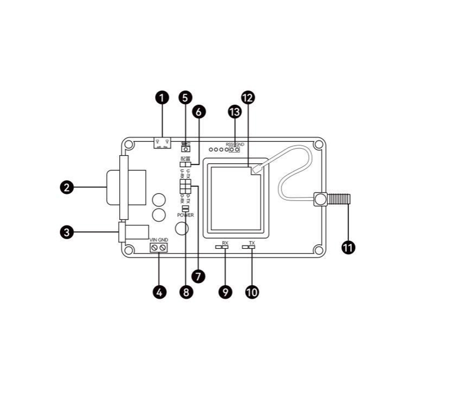
| No. | Interface description |
| ① | Micro USB interface |
| ② | RS232 interface |
| ③ | DC interface, 5~24V DC power supply interface |
| ④ | Terminal block, 5~24V DC power supply interface |
| ⑤ | reset button |
| ⑥ | mode selection port |
| ⑦ | Communication interface selection port |
| ⑧ | Power Indicator |
| ⑨ | Data receiving indicator |
| ⑩ | Data sending indicator |
| ⑪ | SMA-K antenna interface |
| ⑫ | Module installation position |
| ⑬ | Signal Strength Indicator Port |

Practical Application Scenarios
-
Rapid Firmware Debugging and Field Protocol Validation for OEM Engineers
During the initial prototyping stage of embedded RF products, hardware engineers require immediate PC connectivity to test radio link budgets and packet error rates. The RD400D-TB test kit integrates an onboard CH340X USB-to-UART converter, enabling developers to connect the board directly to a PC via Micro USB for real-time AT-command configuration, data stream monitoring, and driver stack validation without building custom breakout boards.
-
Legacy RS232 Industrial Control Equipment Wireless Retrofitting
In industrial automation retrofits, legacy equipment like PLCs, CNC machines, and SCADA terminals communicate strictly via RS232 serial ports. Featuring an integrated WS3232 RS232 interface chip and industrial DC 5V-24V power terminals, the RD400D-TB acts as an instant evaluation bridge, allowing system integrators to test long-range wireless data transmission between two RS232 legacy hosts across the 410-470MHz band.
-
Benchmarking Sub-GHz Wireless Range in Smart Grid and Utility Networks
Before deploying hundreds of remote monitoring endpoints in smart water or power grid networks, field technicians need to evaluate RF performance under real-world terrain obstructions. The test kit exports all RD400D module IOs, mode selection pins, and RSSI signal indicators, permitting engineers to conduct signal strength profiling, range verification, and antenna matching tests prior to final PCB integration.
FAQ Section
-
How do I switch communication between the Micro USB port and the RS232 port on the RD400D-TB evaluation board?
The board features a dedicated communication interface selection port (jumper header). By configuring the shorting blocks according to the pinout silkscreen, developers can route the RD400D module's primary UART signals directly to either the CH340X USB-to-Serial converter for PC debugging or the WS3232 chip for DB9 RS232 serial communication.
-
What are the power supply input requirements when performing 30dBm high-power RF transmission tests?
When the onboard RD400D module transmits at its maximum 30dBm (1W) output, peak current demand increases significantly. The board supports a wide supply voltage range from DC 5V to 24V via either the standard DC barrel jack or 2-pin screw terminal block. It is recommended to use an external power supply providing at least 12V DC / 1A to prevent voltage sag during burst transmissions.
-
Can external host microcontrollers be connected directly to the pin breakout headers on the test kit?
Yes, all IO pins and control lines of the integrated RD400D module are fully routed to 2.54mm pitch breakout headers. Developers can remove interface jumper caps to isolate onboard USB/RS232 translation chips and connect external 3.3V TTL logic signals from STM32, Arduino, or Raspberry Pi microcontrollers directly to the module's UART and control pins.
